
Troubleshooting codes
Read the check-engine light diagnostic blink codes and jump to related TSRM pages.
Use the assistant to choose an area, symptom and TSRM remedy path.
How to check diagnostic codes
For the 7M-GE / 7M-GTE TCCS system, diagnostic problems can be checked by connecting the check connector and counting the number of times the CHECK ENGINE lamp flashes.
Conditions before checking
- Ignition switch ON.
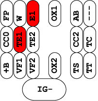
- Check terminals E1 and TE1 connected.
- IDL contacts ON, throttle valve fully closed.
Diagnostic connector
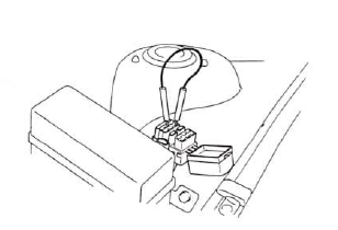
Open the hood and locate the diagnostic connector near the battery. Connect terminals E1 and TE1. A paper clip can be used, but make sure it only bridges the correct terminals.
Normal blink pattern
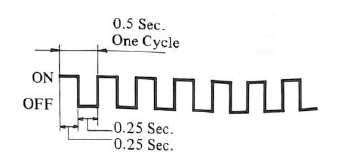
If there is no malfunction, the check engine lamp flashes continuously at about 2 times per second. One normal cycle is about 0.5 seconds.
Malfunction present
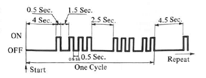
If a malfunction is stored, the lamp flashes the diagnostic code. Count the first group of flashes for the first digit, then the second group for the second digit. In the manual example, codes 13 and 32 are shown.
The pattern repeats. If more than one malfunction is present, the lowest-numbered diagnostic code is displayed first.
Notes
- If two or more malfunctions are present at the same time, the lowest-numbered diagnostic code is displayed first. No other code will appear together with code 11.
- All detected diagnostic codes, except 51 and 53, are retained in ECU memory from the time of detection until cancelled.
- Once the malfunction is cleared, the CHECK ENGINE warning lamp goes out, but the diagnostic code can remain stored in ECU memory, except for codes 51 and 53.
Fault code list
| Code | Item | Diagnosis | Trouble area | CHECK ENGINE light |
|---|---|---|---|---|
| — | Normal | No malfunction stored. | — | — |
| 11 | ECU (+B) | Momentary interruption in power supply to ECU. |
•
Ignition switch, main relay circuit
•
ECU
|
— |
| 12 | RPM Signal | No "Ne" or "G" signal to ECU within several seconds after engine is cranked. |
•
Distributor circuit
•
Crank position, starter signal circuit
•
Distributor
•
ECU
|
○ |
| 13 | RPM Signal | No "Ne" signal to ECU when the engine speed is above 1,000 rpm. |
•
Distributor circuit
•
Distributor
•
ECU
|
○ |
| 14 | Ignition Signal | No "IGF" signal to ECU 6–8 times in succession. |
•
Igniter circuit
•
Igniter
•
ECU
|
○ |
| 21 | Oxygen Sensor Signal | Open circuit in oxygen sensor signal (Ox). |
•
Oxygen sensor circuit
•
Oxygen sensor
•
ECU
|
○ |
| 22 | Water Temp. Sensor Signal | Open or short circuit in water temp. sensor signal (THW). |
•
Water temp. sensor circuit
•
Water temp. sensor
•
ECU
|
○ |
| 24 | Intake Air Temp. Sensor Signal | Open or short circuit in intake air temp. sensor signal (THA). |
•
Intake air temp. sensor circuit
•
Intake air temp. sensor
•
ECU
|
— |
| 25 | Air-Fuel Ratio Lean Malfunction | Oxygen sensor indicates lean condition. |
•
Injector circuit
•
Fuel pressure
•
Oxygen sensor
•
Vacuum leaks
|
— |
| 26 | Air-Fuel Ratio Rich Malfunction | Oxygen sensor indicates rich condition. |
•
Injector circuit
•
Fuel pressure
•
Oxygen sensor
|
— |
| 27 | Sub Oxygen Sensor Signal | Open or short in sub oxygen sensor signal. |
•
Sub oxygen sensor circuit
•
Sub oxygen sensor
•
ECU
|
— |
| 31 | Air Flow Meter Signal | Open circuit in Vc signal or short circuit between Vs and E2 when idle contacts are closed. |
•
Air flow meter circuit
•
Air flow meter
•
ECU
|
○ |
| 32 | Air Flow Meter Signal (7M-GE) | Open circuit in E2 signal or short circuit between Vcc and Vs. |
|
○ |
| 32/2 | HAC Sensor Signal(7M-GTE) | Open circuit or short circuit in HAC sensor signal. |
|
— |
| 34 | Turbocharger Pressure Signal | Abnormal turbocharger pressure signal. |
•
Turbo pressure sensor circuit
•
Turbo pressure sensor
•
ECU
|
— |
| 35 | Turbo Pressure Sensor Signal | Open or short in turbo pressure sensor signal. |
•
Turbo pressure sensor circuit
•
Turbo pressure sensor
•
ECU
|
— |
| 41 | Throttle Position Sensor Signal | Open or short circuit in throttle position sensor signal (VTA). |
•
Throttle position sensor circuit
•
Throttle position sensor
•
ECU
|
— |
| 42 | Vehicle Speed Sensor Signal | No "SPD" signal to ECU for 8 seconds when engine speed is between 2,500RPM and 4,500RPM (7M-GE) or 4,000RPM (7M-GTE) and coolant temp is below 80°C(176°F) and neutral start switch is off. |
|
— |
| 43 | Starter Signal | No "STA" signal to ECU until engine speed reaches 800 rpm with vehicle not moved. |
•
Starter signal circuit
•
Ignition switch, main relay circuit
•
ECU
|
— |
| 51 | Switch Signal | No "IDL" signal or no "NSW" signal or "A/C" signal to ECU, with the check terminals E1 and T shorted. |
•
A/C amplifier
•
A/C switch circuit
•
Neutral start switch
•
Neutral start switch circuit
•
Accelerator pedal and cable
•
Throttle position sensor
•
Throttle position sensor circuit
•
ECU
|
— |
| 52 | Knock Sensor Signal | Open or short circuit in knock sensor signal (KNK). |
•
Knock sensor circuit
•
Knock sensor
•
ECU
|
○ |
| 53 | Knock Control CPU (ECU) | Knock control CPU faulty. |
•
ECU
|
○ |
| 71 | EGR System Malfunction | EGR gas temp below predetermined level during EGR operation. Open circuit in EGR gas temp sensor signal (THG). |
•
EGR system (EGR valve, EGR hose etc.)
•
EGR gas temp sensor circuit
•
EGR gas temp sensor
•
VSV for EGR circuit
•
VSV for EGR
•
ECU
|
— |